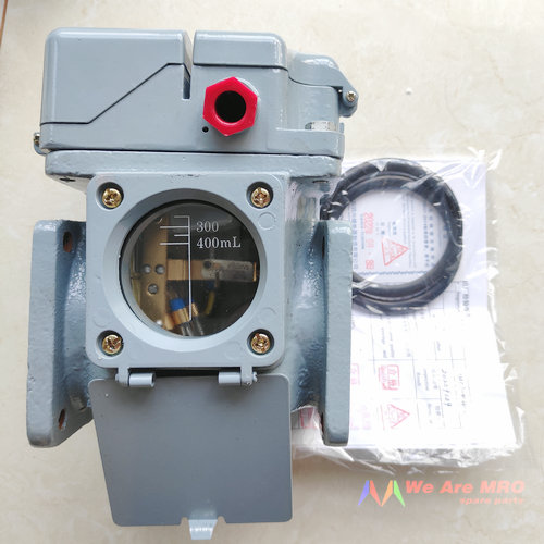
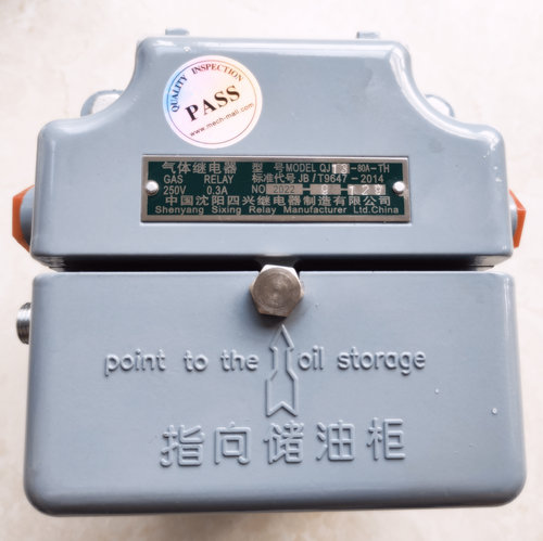
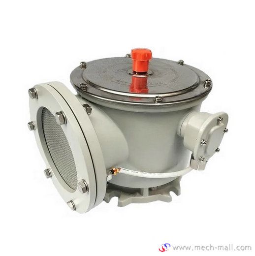
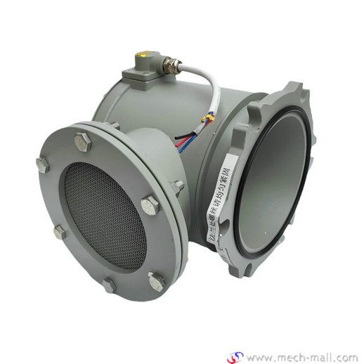
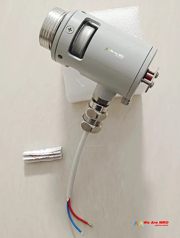
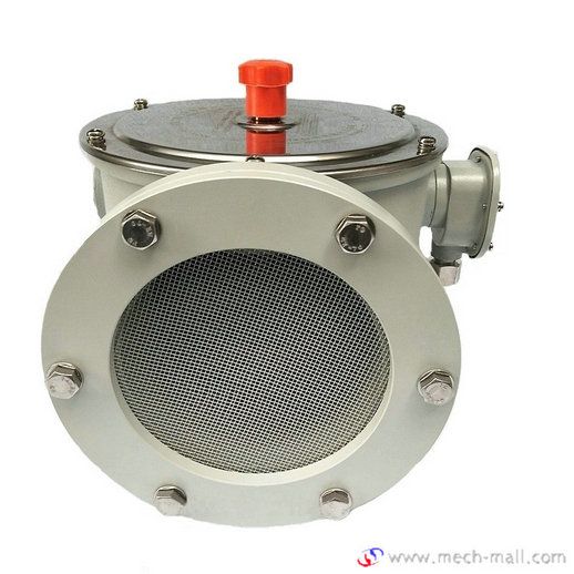
QJ13-80A-TH Buchholz Relay
Usage
Gas oil-immersed transformers and relays are oil-immersed protective devices have a major load tap internal fault. When the gas pipeline connecting thel relay mounted transformer oil conservator, leaving the oil in the transformer internal fault caused by the decomposition of gas or oil flow impulse to make contact action gas relay to turn on the specified control loop, and timely signals or automatic removal of the transformer.
Model Code

Conditions of Use
Allowable operating temperature:-30~+95℃
Installation: The axis of the relay pipeline should be parallel to the transformer cover, and the end leading to the oil conservator is allowed to be slightly higher, but the inclination of the axis and the horizontal plane should not exceed 4%.
Gas Relay (Buchholz Relay) Structure
The structure of the QJ type gas relay is basically the same.
Figure I shows the relay core: The upper part of the relay core is composed of an open cup (float) 3, a weight 2, a magnet4 and a reed contact 5 to form a gas volume device that acts on the signals, the lower part consists of baffle plate 7, spring 11, adjusting screw 10, magnet 6 and reed contacts 8 and 9 to constitute a flow velocity device that acts on tripping. The gas plug I on the cover is used for exhaust air during installation and extraction of faulty gas (Light gas alarm signal) during operation.
Gas Relay Model Table

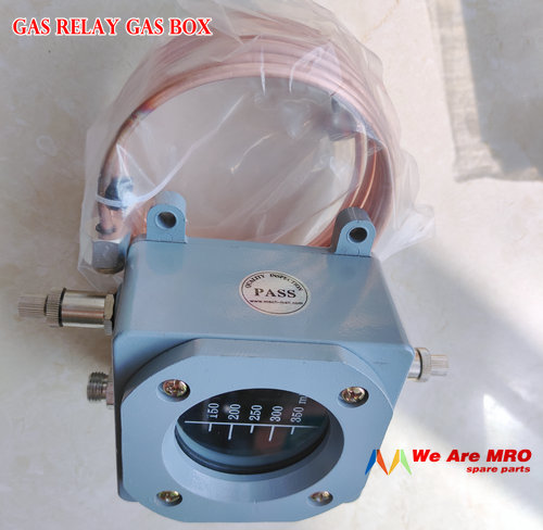
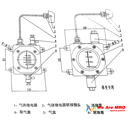
2) Relays with a gas extraction box are marked with "A"at the end of the relay model number, which is not listed in the above table, such as "QJ4-80A".l Users who need it should declare it when ordering.
External structure and installation dimensions
The dimensions of the QJ4-25 relay are shown in Figure 2, the dimensions of QJ-50, 80 relays are shown in Figure 3, See Table 2 for dimensions.


Installation and commissioning
1 Before installation and use of the new relay (QJ-50/80). you must remove the binding tape for transportation and fixing from the flange port. Cut with scissors and take out the cut cord.
2 The relay should be installed in the connecting pipeline between the oil-immersed transformer and the oil conservator. The inner diameter of the connecting pipe should be consistent with the passage (diameter) of the pipeline of the relay. The arrow on the relay must point to the oil conservator. The end of the oil conservator is allowed to be slightly higher, but the inclination of the axis of the coupling pipe to the horizontal plane shall not exceed 4%.
3 The installation position of the relay should be easy to take gas and observe, and to facilitate the maintenance of the relay on the operating site. The installation position should ensure that the relay core can be smoothly taken out from the case. The height of QJ4-25 is 130mm, the height ofQJ4G-25/QJ6-25 is 115mm, and the height of QJ-50 and 80 is 150mm.
4 The electrical wiring is shown in Figure wiring according to the requirements of use, two reed contacts can be used in series, in parallel, or in the same power supply to control the two circuits respectively.
Instructions on relays with memory function
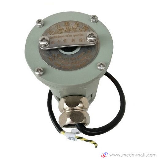
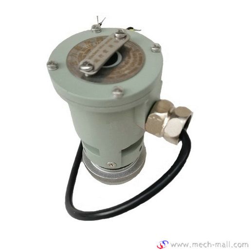
The memory relay is based on the original relay relay on the increase in a red display flag. Under normal circumstances, the sign is vertical. If the relay is tripped by heavy gas, the sign will change and be inclined at an angle of 20 degrees, which can be observed by the on-duty personnel from the inspection window, which is convenient for the on-duty personnel to directly observe the trip of heavy gas, but not for light gas display function. If the switch is closed again, the display mark must be reset manually. Unscrew the protective cap of the relay probe and press the push rod to reset the display mark. The function and usage of Memory relays and Normal relays are the same.
Maintenance and repair
The relay shall be inspected for appearance and reliability of the signal circuit and the reliability of the trip circuit once a year.
The operating relay should be opened every two years to check the internal structure and operation reliability.
A power frequency withstand voltage test should be carried out every five years for relays that have been in operation.
Carry out maintenance and repairs according to actual needs.

